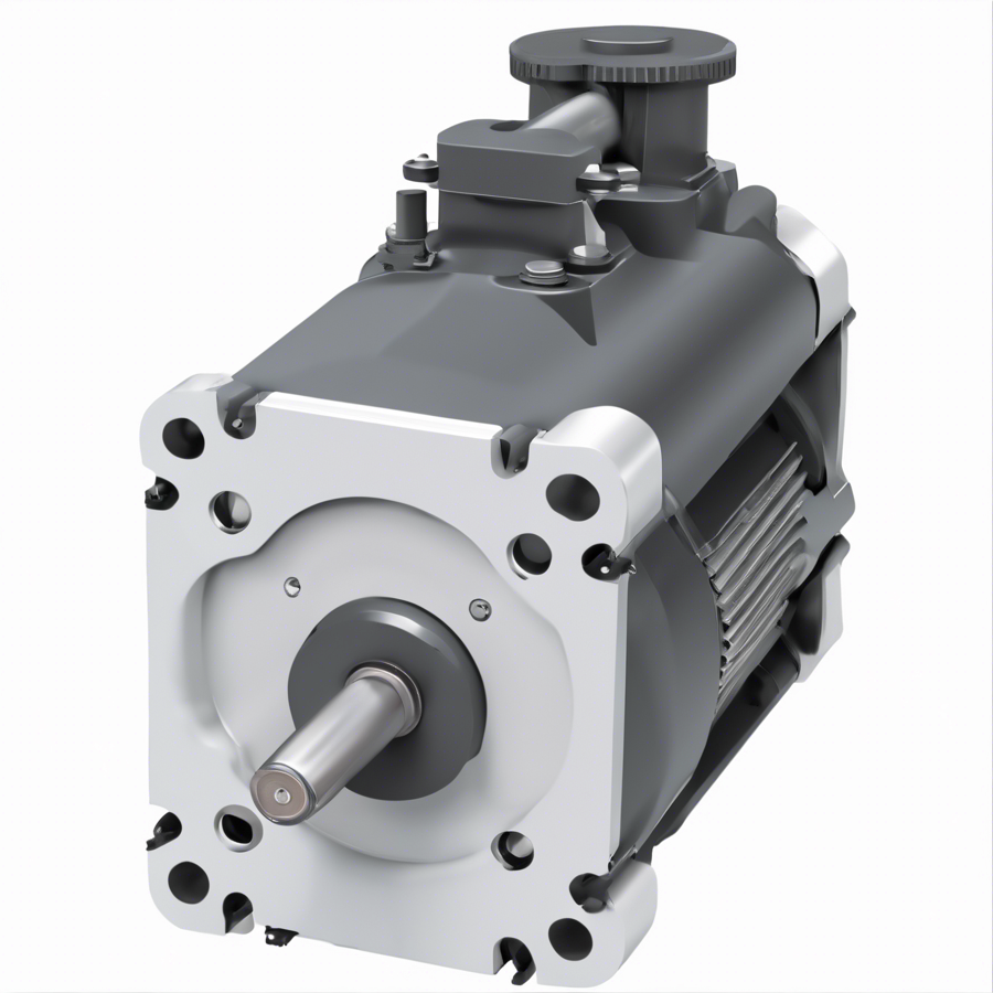
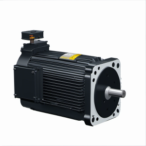
VPL-B1652F-QK12AA SERVO MOTOR; VP SERIES; KINETIX; PERMANENT MAGNET ROTARY MOTOR; LOW INERTIA | Allen Bradley
Type number: VPL-B1652F-QK12AA, Part No.: VPLB1652FQK12AA, from manufacturer: Allen Bradley, Catagory: Kinetix VP Servo Motors Drives & Motors, VPL Low Inertia Motors
della101@163.com
Products Categories
Product Description
| Module No. | VPL-B1652F-QK12AA |
| Product name | SERVO MOTOR; MP SERIES; KINETIX; PERMANENT MAGNET ROTARY MOTOR; LOW INERTIA; 240 VAC; 130 MM FRAME; 3 INCH STACK |
| Product description | VPL-B1652F-QK12AA SERVO MOTOR; VP SERIES; KINETIX; PERMANENT MAGNET ROTARY MOTOR; LOW INERTIA | Allen Bradley |
| Part number | VPLB1652FQK12AA |
| Allen Bradley recommendation product | VPL-B1653D-QJ12AA VPL SERIES; KINETIX; PERMANENT MAGNET ROTARY MOTOR, MOTOR SERVO | Allen Bradley |
| Voltage | 230 VAC, 240 VAC, 480 VAC |
| Manufacturer | Allen Bradley |
| Country of origin | United States |
| Warranty | 1-2 year |
| Shipping Method | 1.Ship worldwide, usually 5-7 days. 2. We use DHL, FedEx, UPS,TNT |
| Remark | If you need a specific firmware or series relating to VPL-B1652F-QK12AA, please call or email us, we probably have it in our large inventory. |
Product Catalogue
VPL-B1652F-QK12AA SERVO MOTOR; VP SERIES; KINETIX; PERMANENT MAGNET ROTARY MOTOR; LOW INERTIA | Allen Bradley
Motor Dimensions (063 mm and 075 mm frame sizes)
Motor Dimensions (063 and 075 mm frame sizes)
Motors are designed to metric dimensions. Inch dimensions are approximate conversions from millimeters. Dimensions without tolerances are for
reference.
Motor
Cat. No.
AD
mm
(in.)
HD
mm
(in.)
LA
mm
(in.)
LD (1)
mm (in.)
(1) If ordering an VPL-A/B063xx or VPL-A/B075xx motor with brake, add 30.6 mm (1.20 in.) to dimension L, LB, LE, and LD.
LE (1)
mm (in.)
L (1)
mm (in.)
LB (1)
mm (in.)
L-LB (2)
mm (in.)
(2) Tolerance for this dimension is ±0.7 mm (±0.028 in.).
D (4)
mm
(in.)
M
mm (in.)
S (3)
mm
(in.)
(3) Tolerance for this dimension is +0.3, -0.0 mm (±0.006 in.).
N (4)
mm
(in.)
P
mm
(in.)
GE (4)
mm
(in.)
(4) For keyway, shaft diameter, and pilot diameter tolerances, see the diagram or Shaft, Pilot, and Keyway Tolerances table above.
F (4)
mm (in.)
VPL-A/B0631
69.5
(2.74) 97.0
(3.82) 9.0
(0.35)
100.2
(3.94)
60.3
(2.37)
143.1
(5.63)
123.1
(4.85)
20.0
(0.787)
9.0
(0.354) 63.0
(2.480)
5.80
(0.234)
40.0
(1.575)
55.0
(2.17)
1.90
(0.075)
3.0
(0.118)
VPL-A/B0632 125.2
(4.93)
85.3
(3.36)
168.1
(6.61)
148.1
(5.83)
VPL-A/B0633 150.2
(5.91)
110.3
(4.34)
193.1
(7.59)
173.1
(6.81)
VPL-A/B0751
77.0
(3.03)
112.0
(4.41)
9.0
(0.35)
102.0
(4.02)
62.1
(2.44)
147.9
(5.82)
124.9
(4.92)
23.0
(0.906)
11.0
(0.433)
75.0
(2.953)
5.80
(0.234)
60.0
(2.362)
70.0
(2.76)
2.60
(0.102)
4.0
(0.157)
VPL-A/B0752 127.0
(5.00)
87.1
(3.43)
172.9
(6.80)
149.9
(5.90)
VPL-A/B0753 152.0
(5.98)
112.1
(4.41)
197.9
(7.79)
174.9
(6.89)
N
LD
HD
P
26.6
(1.05)
AD
LA
LB L-LB
L
D
LE
LD
F
GE
See Detail A
Shaft Detail
with Key
Shaft Diameter Tolerances
VPL-A/B063xx Motors:
Ø 8.998…9.007 (0.3543…0.3546)
VPL-A/B075xx Motors:
Ø 10,997…11.008 (0.4330…0.4334)
Detail A
Shaft
Diameter Optional Shaft Seal
Refer to page 22
for motor shaft seal
kit information.
Single (M23)
Motor Connector
S Diameter Holes on
M Diameter Bolt Circle
Dimensions are in mm (in.)
Connector housings can be
rotated within a range of 325°
Pilot Diameter Tolerances
VPL-A/B063xx Motors:
Ø 39.995…40.011 (1.5746…1.5752)
VPL-A/B075xx Motors:
Ø 59.993…60.012 (2.3619…2.3627)
Shaft, Pilot, and
Keyway Tolerances VPL-A/B063xx VPL-A/B075xx
Shaft Runout (T.I.R.) 0.030 (0.0012) 0.035 (0.0014)
Pilot Eccentricity (T.I.R.) 0.08 (0.0031) 0.08 (0.0031)
Max Face Runout (T.I.R.) 0.08 (0.0031) 0.08 (0.0031)
Keyway Depth (GE) 1.80…1.90
(0.071…0.075)
2.50…2.60
(0.098…0.102)
Keyway Width (F) 2.971…2.996
(0.117…0.118)
3.970…4.000
(0.156…0.158)
Shaft-end
Threaded Hole
Thread – M3 x 0.5-6H
Thread Depth – 9.0 (0.354)
Thread – M4 x 0.7-6H
Thread Depth – 10.0 (0.393)
Key Supplied
VPL-A/B063xx = 3(+0, -0.025) x 3 (+0, -0.025) x 13 Key
VPL-A/B075xx = 4(+0, -0.030) x 4 (+0, -0.030) x 15 Key
Pilot Diameter (N)
Optional Shaft Seal
Fully Developed Keyway Length
VPL-A/B063xx Motors: 14.0 (0.551)
VPL-A/B075xx Motors: 16.0 (0.630)
Pilot Height
2.1 (0.083)
0° ±10° Shaft-end mark (or key)
orientation for encoder
absolute position = 0.
Shaft-end
Threaded Hole
Related Products
