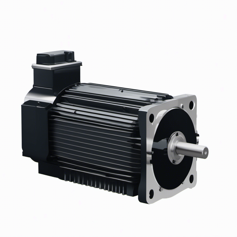
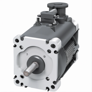
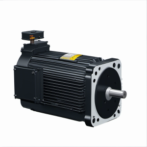
VPL-B1653D-QJ12AA VPL SERIES; KINETIX; PERMANENT MAGNET ROTARY MOTOR, MOTOR SERVO | Allen Bradley
Type number: VPL-B1653D-QJ12AA, Part No.: VPLB1653DQJ12AA, from manufacturer: Allen Bradley, Catagory: Kinetix VP Servo Motors Drives & Motors, VPL Low Inertia Motors
della101@163.com
Products Categories
Product Description
| Module No. | VPL-B1653D-QJ12AA |
| Product name | SERVO MOTOR; MP SERIES; KINETIX; PERMANENT MAGNET ROTARY MOTOR; LOW INERTIA; 240 VAC; 130 MM FRAME; 3 INCH STACK |
| Product description | VPL-B1653D-QJ12AA VPL SERIES; KINETIX; PERMANENT MAGNET ROTARY MOTOR, MOTOR SERVO | Allen Bradley |
| Part number | VPLB1653DQJ12AA |
| Allen Bradley recommendation product | MPL-A1510V-EJ42AA Premium permanent magnet rotary servo motor | Allen Bradley |
| Voltage | 230 VAC, 240 VAC, 480 VAC |
| Manufacturer | Allen Bradley |
| Country of origin | United States |
| Warranty | 1-2 year |
| Shipping Method | 1.Ship worldwide, usually 5-7 days. 2. We use DHL, FedEx, UPS,TNT |
| Remark | If you need a specific firmware or series relating to VPL-B1653D-QJ12AA, please call or email us, we probably have it in our large inventory. |
Product Catalogue
VPL-B1653D-QJ12AA VPL SERIES; KINETIX; PERMANENT MAGNET ROTARY MOTOR, MOTOR SERVO | Allen Bradley
N ISO 13849-1, IEC EN 61508, and EN 62061 standards for complete information on the requirements for PL and SIL
determination.
Safety-related Parameters
A motor that is equipped with a Hiperface DSL functional safety-rated feedback sensor is designed to maintain the functional safety rating of the
feedback sensor attached. The safety parameters of the feedback sensors are as follows.
Motor Installation
Motor installation must comply with all local regulations and use of equipment and installation practices that promote safety and electromagnetic
compatibility:
• All motors include a mounting pilot for aligning the motor on a machine.
• Preferred fasteners are stainless steel.
Change Connector Orientation
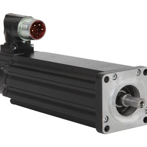
Kinetix VP low-inertia motors use a connector style that integrates the power, brake, and feedback signals within a single connector. You can
identify the connector style by the variable number in the motor catalog string. For example, in catalog number VPL-A1303F-CJ12AA, the 1
indicates a SpeedTec, right-angle, 325° rotatable connector (see Catalog Number Explanation on page 2).
The rotatable connector housing lets you move the connector into a position that best protects the connection from environmental contaminates
and provides easy access.
Attribute Motor Cat. No.
VPL-xxxxxx-Wx1xAx VPL-xxxxxx-Qx1xAx
Safety Integrity Level (SIL) SIL2 (IEC 61508), SIL CL2 (EN 62061)
Probability of a Dangerous
Failure per Hour (PFH) 4.0 E-08 1/h 3.80 E-08 1/h
Safety Category CAT. 3 (EN ISO 13849)
Performance Level (PL) PLd (EN ISO 13849)
ATTENTION: Unmounted motors, disconnected mechanical couplings, loose shaft keys, and disconnected cables are dangerous if power is applied. Identify (tag-
out) disassembled equipment and restrict access to (lock-out) the electrical power.
Before applying power to the motor, remove the shaft key and other mechanical couplings that could be thrown from the shaft.
ATTENTION: Verify that cables are installed and restrained to prevent uneven tension or flexing at the connector. Provide support at 3 m (10 ft) intervals
throughout the cable run.
Excessive and uneven lateral force at the cable connector can result in the connector’s environmental seal opening and closing as the cable flexes.
ATTENTION: Connectors are designed to be rotated into a fixed position during motor installation, and remain in that position without further adjustment.
Strictly limit the applied forces and the number of times the connector is rotated to make sure that connectors meet the International Protection (IP) rating as
outlined in Environmental Specifications on page 22.
ATTENTION: Excessive force can damage the connector. Do not pull on the cable and do not use tools, such as pliers or vise-grips, to rotate the connector. Use
your hands to rotate the connector.
Related Products

